De
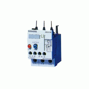
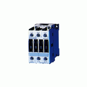
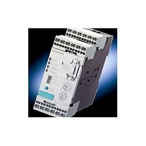
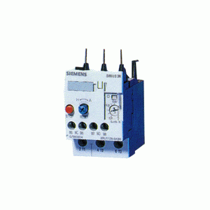
3RU11 overload relays belong to the new generation of SIRIUS 3R control products. The 3RU11 overload relays replace the highly successful 3UA5 and 3UA7 devices. Outstanding features of the new overload relays include long term stability and long service life. The overload relays are optimally matched, both electrically and mechanically, to the 3RT10 contactors. They can also be mounted as a single unit with the use of a separate mounting bracket. 3RU11 overload relays cannot be mounted onto 3TF contactors.
The 3RU11 overload relays are available in four distinct
Application
3RU11 overload relays provide overload protection for three-phase inductive motors with rated currents of up to 100A (75HP, AC-3, 480V). They are used in conjunction with 3RT10 contactors to form motor starters.
Ambient conditions
Thanks to the newly integrated bimetal and continuous temperature compensation, these devices can be used without derating at an ambient temperature of up to 60°C (140°F).
Use up to 70°C (158°F) is possible with derating.
Auxiliary contacts
The overload relays are equipped with a NC contact for de-energizing the contactor and a NO contact for signalling an overload trip. The breaking capacity of the switching contacts is very high so that the contactor coils can be switched directly.
Trip class
The 3RU11 overload relays are designed in accordance with trip class 10 i.e. trips in less than 10 seconds at 6 times the trip current setting (FLA).
Phase failure sensitivity
A phase failure sensitivity function is integrated in order to provide increased protection in the event of a phase failure, i.e. faster tripping in the event of a single-phase condition.
Setting the overload relay
The current setting dial can be accessed once the transparent, sealable cover has been opened. The overload relay must be set at the rated full-load amps (FLA) of the motor.
STOP function
Pressing the red STOP button on the overload relay momentarily opens the NC trip contact. No other contacts and/or functions are affected by this STOP button.
Manual/automatic reset
The RESET button/mechanism features tripfree operation. This means that the overload relay will trip on an overload condition regardless of whether the reset button is pushed in or not. Manual or automatic reset can be selected with the blue button. The appropriate setting is selected by pressing and turning the button. This setting can then be locked by the sliding transparent cover.
TEST function and switch position indicator
The switch position indicator also incorporates a test function which, when activated, simulates a tripped overload relay. Both auxiliary contacts are actuated and the switch position is indicated.
Terminal for contactor coil and auxiliary contact
When the 3RU111 overload relay is mounted directly on the contactor, the auxiliary contact terminal and the coil terminal A2 of the contactor are fed through to the bottom side of the overload relay. This helps considerably in expediting the wiring for both new and retrofit applications. The carry through of the A2 coil terminal to the bottom of the overload relay is not necessary with the 3RU112, 3RU113, and 3RU114 devices since the associated contactors are equipped with four point coil connections and the auxiliary contacts are either front or side mounted.
Cage Clamp connection
3RU11 overload relays are available with Cage Clamp terminals. 3RU111 overloads have Cage Clamps on the auxiliary and power terminals. 3RU112, 3RU113, and 3RU114 overloads, however, have Cage Clamps on the auxiliary terminals only. The power terminals on 3RU112, 3RU113, and 3RU114 overloads must remain screw type.
Accessories
The accessories available are suitable for use with all
· Electrically operated remote RESET available in different voltages
· Plunger type mechanical RESET for new and existing enclosure installations
· Flexible cable type RESET mechanism for applications where the devices are not easily accessible
Environment
The devices are manufactured using environmentally-friendly and recyclable materials only.
Specifications
IEC 947-1, IEC 947-5-1, and DIN VDE 0660. 3RU11 overload relays are suitable for use in any climate when used with the correct enclosure.
The devices are shock-hazard protected to DIN VDE 0106, Part 100.
Approvals
UL, CSA, CE marked.


 Company


