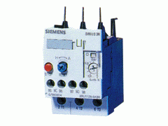
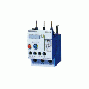
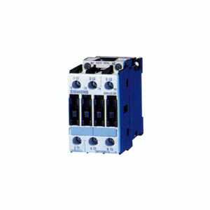
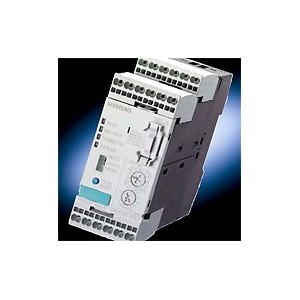
Specifications
· IEC 947-4-1, IEC 947-5-1 and DIN VDE 0660. UL Listed File #E22655.
· The devices are shock-hazard protected according to DIN VDE 0106, Part 100.
General
The 3RB10 overload relays form part of the new SIRIUS 3R control generation. The solid-state version of the SIRIUS 3R overload relay is noted for its wide overload ranges (setting ratio 4:1), for its phase loss protection and also for the minimal energy requirement. In terms of dimensions and termination, the solid-state (3RB10) and the thermally delayed types (3RU11) are 100% compatible. Conformal coating of the printed-circuit board and of the electronic components assures reliable operation even in aggressive and tropical atmospheres. Four sizes and two variants are available up to 100A. The overload relays are optimally matched, both electrically and mechanically, to the 3RT10 contactors. They can, however, also be mounted separately with an adapter for installation as a single unit. Devices up to and including size S0 can be fitted on standard mounting rails without using tools.
Application
3RB10 solid-state overload relays provide overload protection for three-phase induction motors with rated currents of up to 100A.
For short-circuit protection with fuses or circuit- breakers, the fusing values of the contactors must be taken into account.
Operation
The solid-state overload relays have been developed for use in sinusoidal 50/60Hz voltage networks. These units are self-powered and require no additional power supply for operation. Current transformers (for measurement) are already integrated. A microprocessor checks the current values of each phase and initiates release in the event of overload or phase failure.
The tripping current corresponds to 110% of the set current.
The overload relay must be set to the rated motor current.
Trip classes
The devices are available in Class 10 (motor starting times up to 10 s.) and in Class 20 (motor starting times up to 20 s.) trip curves.
Phase-loss protection
The 3RB10 solid-state overload relays are equipped with phase-loss protection. If a phase loss occurs, the device trips within three3 seconds.
STOP function
Activating this function only affects the NC contact, momentarily changing the state of the contact.
Manual/automatic reset
Manual or automatic reset can be selected with the blue button. The appropriate setting is selected by pressing and turning the button.
TEST function and switch position indicator
The switch position indicator also incorporates a test function which, when activated, simulates a tripped overload relay.
Both auxiliary contacts are actuated and the switch position is indicated.
Terminal for contactor coil and auxiliary contact
When the 3RB1016 overload relay (size S00) is mounted directly on the contactor, the auxiliary contact and coil terminal A2 of the contactor are fed through to the bottom of the overload which simplifies wiring.
This is not necessary with size S0 as the contactors are equipped with four coil terminals.
Auxiliary contacts
The overload relays are equipped with a NC contact for disconnecting the contactor and a NO contact for signalling tripping. The breaking capacity of the switching contacts is very high so that the contactor coils can be switched directly.
Mounting
The overload relays are mounted directly on the 3RT10 contactors. If they are fitted individually on a connector base, they can be fastened by means of screws or placed on a mounting rail. The connector bases of the 3RU11 thermally delayed relays can be used.
Accessories
The accessories used with the 3RU11 thermal overload relays can be used for the 3RB10 solid-state overload relays.
· Reset plunger to extend the through-the door reset button on deep panels
· Flexible cable reset mechanism for overloads which are not easily accessible


 Company


